How safe are emergency shutdowns in real life?
Appropriate use of various layers of protection
Decisions in the design of process and control systems are often based on the assumption that emergency shutdowns are always the safe response to upsets and maintain the asset integrity. However, they may impose significant risks to the plant and personnel. Alternative intervention actions and design decisions may provide less risky solutions.
Emergency shutdowns (ESDs)
An emergency shutdown is meant to turn a potentially hazardous process condition into a ‘safe state’, but such a shutdown can cause considerable problems, both during the shutdown itself and during the subsequent restart.
The international standards on functional safety (IEC 61508 and IEC 61511) have become broadly accepted. A ‘safe state’ according to IEC 61511 is the state of the process when safety is achieved, as defined as freedom from intolerable risk. However, some states are safer than others and while going from a hazardous condition to the final safe state, the process may have to go through several intermediate ‘safe states’, which may be less safe. For example, a pump trip may cause no flow conditions downstream, or even backflow, which might create high level conditions in upstream vessels. Many ESDs trade one type of process upset for another that hopefully has a less severe repercussion.
Modern plant design is typically based on high levels of automation and (often) low levels of involvement for operators. Start-ups and shutdowns may well be exceptions to this rule, where operators need to make extensive and critical decisions. This process is often not given much careful thought in design or operational review. It can significantly worsen the risks associated with shutdown or start-up.
Plants are basically designed for normal operations with safeguards against abnormal conditions. However, the transient from normal operating conditions to shutdown conditions may contain several dangerous intermediate conditions, especially related to upstream or downstream process units. Operators may need to improvise non-standard operations and are more likely to take an unsafe decision due to stress.
The US Chemical Safety and hazard investigations Board have published an overview on their website (www.csb.gov) of all the incident investigations they carried out. Several incidents happened while a process unit was in or was being brought into a safe shutdown situation. Two incident examples are given in the text box on the next page.
Examples of incidents during ‘safe mode’
Explosion at the ExxonMobil Refinery (Torrance, California in 2015)
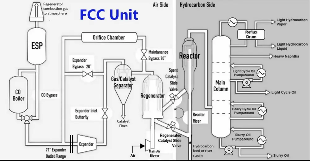
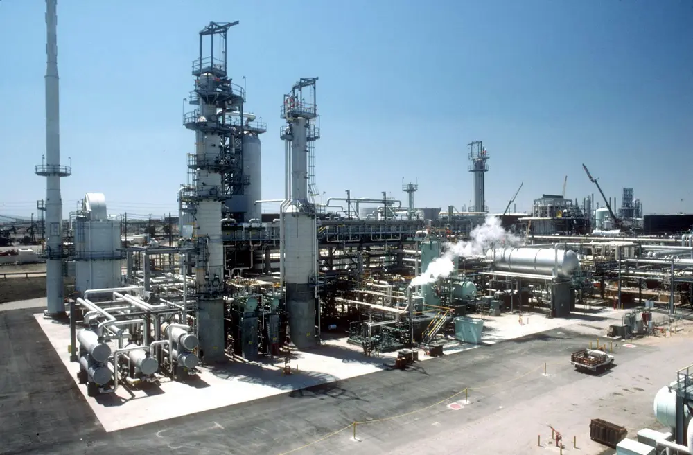
The refinery’s Fluid Catalytic Cracking Unit (FCCU) was put in bypass mode to allow maintenance on the expander in the unit. In this unit slide valves must maintain a catalyst barrier between a reactor, which contains flammable hydrocarbons, and a regenerator, which contains air. During this safe mode the feed flow and air flow were halted and the slide valves were both closed to maintain a catalyst barrier in between. Steam was injected in the reactor to prevent backflow from hydrocarbons. However, the electrostatic precipitation (ESP) unit in the flue gas section, which is generating sparks to burn the CO, was left on. One of the slide valves was leaking, so there was no effective catalyst barrier between the air and hydrocarbons. After the maintenance, the expander could not be started and it was assumed that catalyst had accumulated on the expander. When opening a flange at the expander to install a blind, steam was flowing through the opening, while the catalyst barrier did not function. It was decided to reduce the steam flow to the reactor to minimize the escaping steam. This allowed the backflow of hydrocarbons from the distillation column to mix with the air in the pipeline from the regenerator to the ESP unit, where the explosion took place.
Explosion and fire at the Husky Refinery (Wisconsin, US in 2018)
The initial explosion occurred in the FCCU during shutdown for periodic maintenance and inspection. Here too the slide valves were leaking which allowed backflow of air from the regenerator to the reactor, leading to an explosive mixture with flammable hydrocarbons from downstream the reactor. The mixture flowed back to the regenerator combustion gas section, where the explosion took place with devastating consequences.
Layers of protection
It has always been sound engineering practice to have two independent layers of protection, one for control and one for safeguarding (i.e. ESDs). To minimize the demand on ESDs we may extend this approach. The core concept here is to design layers of control protection in which less drastic actions take priority. This way you end up with a process control system – at least for your most critical control loops – with a structure like this:
• Layer 1: Regular controllers and interlocks
• Layer 2: Protective controllers
• Layer 3: Engineered process alarms with operator intervention
• Layer 4: Process shutdowns and operator actions (cutback systems)
• Layer 5: Emergency shutdowns
The following paragraphs describe these layers in more detail.
Layer 2: Protective controllers
Protective control uses dedicated controllers, which normally do not act. They have their own control valves, or they may override other regular controllers with their control valves. Protective controllers are usually implemented in the DCS but are mandatory forced in automatic mode, and their setpoint cannot be changed by the operator (or can only be changed within a small range). Protective controllers will act during process upsets, e.g. when regular control loops fail. They usually will act before alarms are raised with operator intervention, because they have automated control actions. They certainly will act before an ESD will happen.
One common example is the minimum flow protective controller for pumps. The protective flow controller opens the control valve in the recycle line to prevent pump damage when the flow through the pump falls below the required minimum (and to prevent a low flow emergency shutdown of the pump).
Protective control is a relatively simple and cheap method to prevent ESDs, and allow the operator to bring back the process into its normal operating window. Protective control is not always shown on licensor’s P&IDs, but must be added during detailed engineering by the engineering contractor or the end-user representatives during the design phase of a project.
Layer 3: Engineered process alarms with operator intervention
In engineered process alarms with operator intervention there is considerable room to make the protection layer more robust. It comes in terms of improved operator training and procedures. Or as it is stated by the Institute of Hazard Prevention in Calgary, Canada: “Your people are your strongest risk management assets. They make up 40% of the safeguards. Invest in them, reduce risk, promote safety and achieve operational excellence.”
In general, there has been a very strong tendency to derogate operator intervention as an ineffective protective layer. But when we look at some of the industries that have achieved the most extensive reduction in risk in the last century, like civil aviation, they place considerable trust in that human layer, but it has been backed up with rigorous training including the use of flight simulators. We as engineering contractors have seen the development of ‘Alarm management’. It started in 1999 with EEMUA publication 191: ‘Alarm systems: A Guide to Design, Management and Procurement’. EEMUA is the Engineering Equipment and Materials Users’ Association, representing the major players in the process industry. This publication defines the rules of how to engineer alarms that are effective and advice the operator what to do when. Alarms are to be prioritized based upon the operator response time and the consequence if no action was taken. Limited alarms are allowed per time unit in order not to overload the operator by applying different alarm filtering and suppression mechanisms.
The publication has been adapted by ANSI/ISA 18.2 standard in 2009 (and the IEC standard 62682 in 2014). Both standards have the title: ‘Management of Alarm Systems for the Process Industries’. Operator training simulators have been developed using the actual software in the DCS to increase the effectiveness of the operators in handling the alarm conditions in the process.
Layer 4: Process shutdowns and operator actions (cutback systems)
Process shutdowns are an additional layer of protection to prevent emergency shutdowns. During one of our engineering projects for a residue hydrocracking unit we have developed a so called automatic ‘Cutback system’, which basically is a combination of various process shutdown functions with operator actions.
Residue hydrocracking is used to upgrade the residue from a Vacuum Crude Distillation unit into more valuable products. There are different technologies, but they all have severe operating conditions: high reactor temperature and pressure (more than 400 °C and more than 120 barg). In the reactor there are endothermic cracking reactions and exothermic hydrogenation reactions, which always must be kept in balance. Process upsets may cause very high temperatures and excessive coking. Emergency shutdowns do not solve the problem, they just stop the process. They may even become prolonged due to the excessive coking just before and during the ESD.
The Cutback system is intended to supplement but not completely replace an ESD system. Cutbacks are designed to avoid those potentially hazardous conditions requiring full shutdown and significant unit downtime. They will default the process unit into a safer state of operation to prevent emergency shutdowns. Then the operator is allowed to resolve the process upset and subsequently resume normal operations.
The Cutback system can be initiated by any one of the following conditions (listed with increasing priority):
1. Loss of make-up gas flow
2. Reactor high skin temperature criteria (detecting maldistribution)
3. Loss of liquid flow
4. Partial loss of recycle gas flow
5. Reactor temperature high (H)
6. Total loss of recycle gas flow
7. Total loss of recycle and make-up gas flow
8. Reactor temperature very high (HH)
Each initiating condition has a selection of different available actions with different parameters (i.e. setpoint values) based upon the severity of the condition. Initiating conditions of higher priority may interrupt the actions by initiating conditions with lower priority, while more severe are required.
The Cutback system has the following actions available:
1. Reducing liquid feed temperature (by decreasing the setpoint of liquid heater outlet temperature controller, or by activating the minimum firing of the liquid heater depending on the severity of the initiating condition)
2. Introducing alternative liquid feed (by ramping up the setpoint of the alternative liquid)
3. Reducing recycle gas temperature (by decreasing the setpoint of recycle gas heater outlet temperature controller, or by activating the minimum firing of the recycle gas heater depending on the severity of the initiating condition)
4. Introducing alternative make-up gas (by ramping up the setpoint of the alternative gas)
5. Reactor controlled depressurization (by simultaneously ramping down the setpoint of various pressure controllers to different settings depending on the severity of the initiating condition).
The exact relation between the initiating conditions and the available actions is documented in a Cause and Effect Matrix. The Cutback system is implemented in the DCS with independent instrumentation to minimize common cause failure. Most instrumentation is redundant to prevent spurious activation. Each initiator has a short time delay to allow the operator to intervene in case the process is already in a transient condition being supervised by the operator and the Cutback system does not need to get in operation.
As mentioned before, the Cutback system does not replace the ESD system, so when emergency conditions become more severe (i.e. reactor temperature extremely high (HHH)), then the Cutback system is overruled and the usual emergency shutdown actions are executed. However, this will happen less often than without the Cutback system.
Concluding remarks
There is usually room for systematic identification of less drastic safeguarding actions before an ESD. In fact, even assuming that the shutdown of a process unit or a facility can be accomplished in perfect safety, bringing the system back online can often be a risky proposition, particularly given the substantial costs that downtime can impose on a facility restart.
Further, the shutdown itself may impose significant risks. In many cases, less drastic process control and safeguarding actions may be available and significantly less risky.